Column Slab & Beam Lap Lengths - Types & Methods

Due to the inaccessibility of longer bars that need to extend, lap length requires when bars are placed short of their required length. Changing the bar diameter along the length requires a change in lap length. By using Lap, the terminating bar's axial force can be transferred to the connecting bar in the same manner as it transfers in the junction.
Concrete in the surrounding area is invariably stressed. When splicing, use proper splicing techniques, avoid high flexural and shear zones in a column, and stagger the splice points at every individual bar to mitigate the effects of these stresses.
Types of Lapping Method
Slab Lap Length
Side face reinforcement should be provided along with the two faces of a beam if the depth of the web at the beam exceeds 750 mm. This reinforcement must not be less than 0.1 percent of the total web area, and it must be evenly distributed over the web, not exceeding 300 mm between faces, whichever is less.
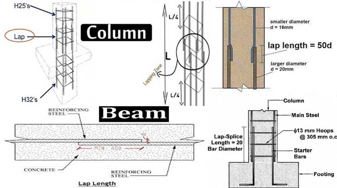
Beams have a 60-diameter lap length. The outermost tension and compression bars of beams must reinforce in transverse directions. Such reinforcement requires T- and I-beams near the outer face of the flange.
Beam Lap Length
One-eighth of the slab's thickness shall not exceed the diameter of the reinforcing bars. A slab must have a minimum of 0.15 percent mild steel reinforcement in either direction. When welded wire fabric or high-strength deformed bars are used, this value can reduce to 0.12 percent.
Column Lap Length
At least 12 mm in diameter must be the minimum for bars. Columns of rectangular and circular shapes should have at least six longitudinal bars. At least 300 millimeters must separate longitudinal bars along the column's perimeter.
Rebar Lap Length
Rebar Lap length refers to the amount of overlap between two bars. Where the bending stress is the least, lapping performs usually. It generally accepts that if both bars are of equal diameter, the lap length is 50d or equal to 50 times their diameters.
Methods of Lapping
Lap Splices
Lap splices are designed to transfer some of the axial force from the terminating bar to the connecting bar through anchorage bonds with the concrete. Tests on lap splices found similar behavior to tests on anchorage bonds in terms of splitting and cracking. The bend should be slight, especially near the splice location, to ensure a collinear and non-eccentric force transfer.
The lap length should be calculated for bars of different diameters to be spliced based on the smaller diameter. A spiral made of 6mm diameter bars not exceeding 10mm inches in pitch shall surround each splice in tension members.
Welded Splices
For bars with large diameters, welded splices are recommended. Consequently, steel reinforcing consumption reduces. It is desirable to tension tests to ensure the adequate strength of such splices.
A welded splice is usually made by welding the bars together at the bottom. It is important to splice bars of the same diameter.
In addition to two or three additional small diameter lap bars symmetrically positioned to the main bars, symmetrically positioned lap bars can also be provided. A suitable bearing plate welders to the bar ends, and the ends of the bars square cut into the concrete cover.
Wrapping Up
Larger diameter bars may be welded; bar splices greater than 36 mm should not be lapped; when welding cannot be done, larger diameter bars may be lapped with additional spirals.
If there are more than two bars in contact, the development length shall be increased by 10 percent, 20 percent, and 33 percent for each additional bar in contact.
To learn more, watch the following video tutorial.
Video Source: Civil Engineers